Jamara Mosquito build log
Planned set-up:
·
Two pumped dykes ringed Webra speed 40 with dynamix carbs
from the good old eighties fed from a single large fuel tank in the central
bomb compartment. Side mounted. I will attempt 11x5 or 12x5 props. Bisson pitts
style mufflers.
·
Spinners from Traplet:
http://shop.traplet.com/product.aspx?c=2619;
they are for the Brian Taylor 71 inch Mosquito and they are a few mm too small.
·
Gear mechanics from e-flite;
the 60-120 gear appear sturdy enough.
·
Homemade struts.
·
CG at 110 mm behind wing root by the fuse
measured under the wing.
·
Something like 2 degree outwards thrust on
the right engine and 1 degree outwards thrust on the left engine as interpreted
from a description somewhere in the thread in order to make handling on one
engine “easier”…
Before you start…
The last section contains a list of things
that I would perhaps have done differently if I made a second build.
Now over to construction…
Strengthening of the firewall and gear mount
Test fit of the landing gear mechanics. It seems fragile for a ~6 kilo plane...
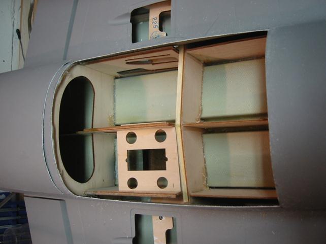
Cutting out the gear mount...
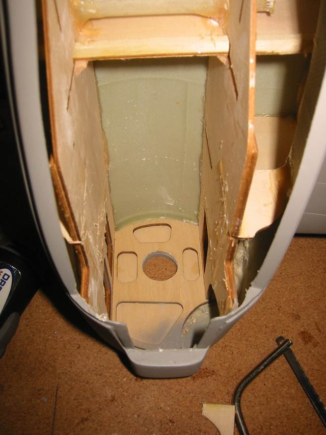
Notice something? No Glue and almost intended weak spots (light holes) in the sides holding behind the firewall. No surprise that the engines fall off easily... Some strength will be added. Considering how easy it was to clean out the compartment I take my hat off for those who manage more than a few flights without these parts failing.

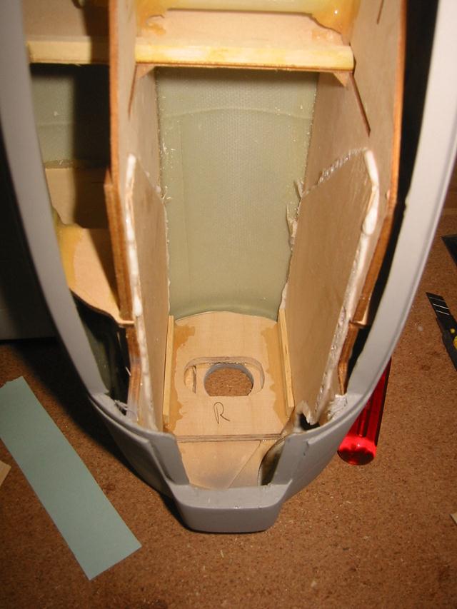
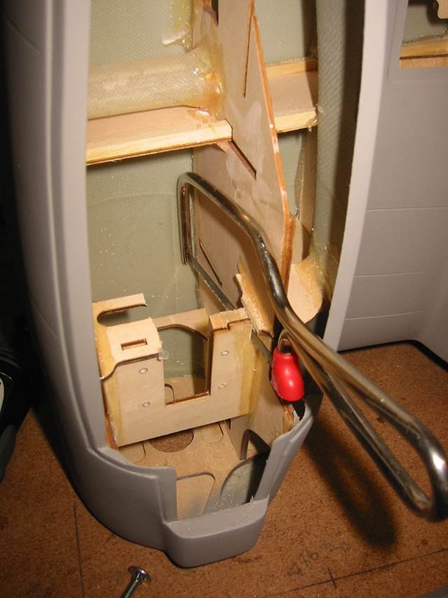
Now this feels like it’s going to cut it. About 50 grams added, all in front of the CG. The obvious weak spot is now by the arrow; I guess this slot is required for assembly at the factory...
Before I add the
gear mounting plate I have to decide a few things; 90 degree gear mechanism and
having the wheel slightly visible when up or 105 degree mechanics..?
I’ll have to think about it but the easy way is wheel slightly visible...
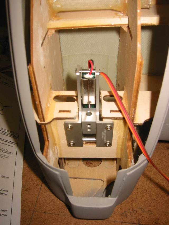
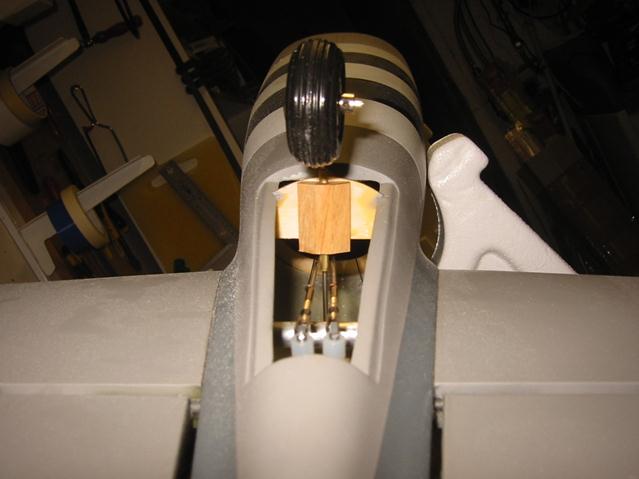
I went for the 90 degree gear mechanics and slightly visible wheel...
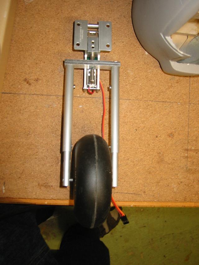
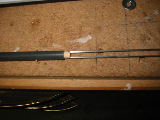
Complete gear mechanics with custom strut and wheels.
Mounted retracts. Note that the space for the gears in the ply structure is not centred in the nacelle. I suppose this has to be put on the account of “non-scale features”... The 100mm wheel is a dubro inflatable; quite heavy and perhaps overkill. I will see when it comes to CG adjustment whether I change for a lighter set. As you can see everything is ready for test... a video is available on http://hansenm.web.cern.ch/hansenm/planes/JamaraMosquito/gear_test.AVI. The video can be safely played with media player (3MB).
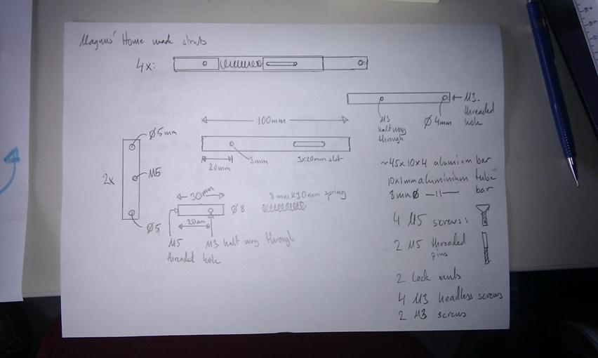
Drawing of the parts for the struts. Indeed it needs some interpretation. The location of the slot etc need to be changed according to the actual hardware you find.
Now to the next item:
Tank in the bomb compartment
Clearly the space available is going to use the space intended for the flap servo that will have to be relocated. The tank will end up behind the CG, thus balance CG with tank full, please...
The lid with formers.
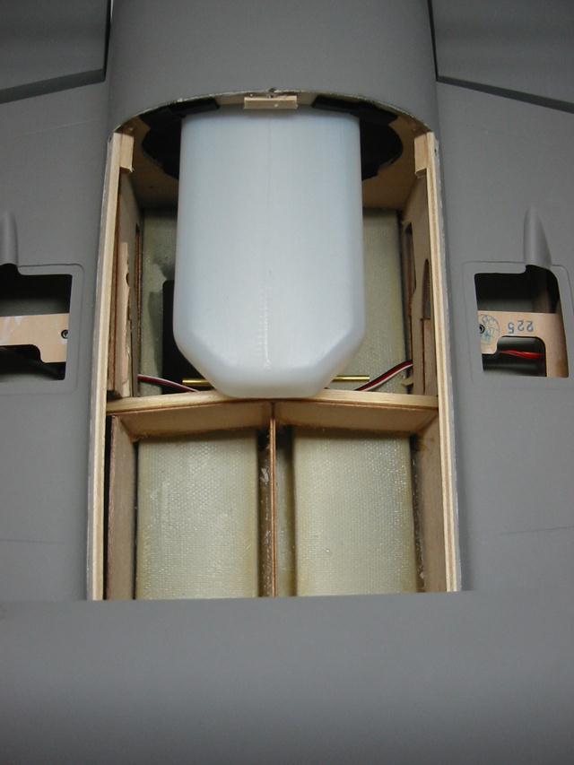
20oz tank in place.
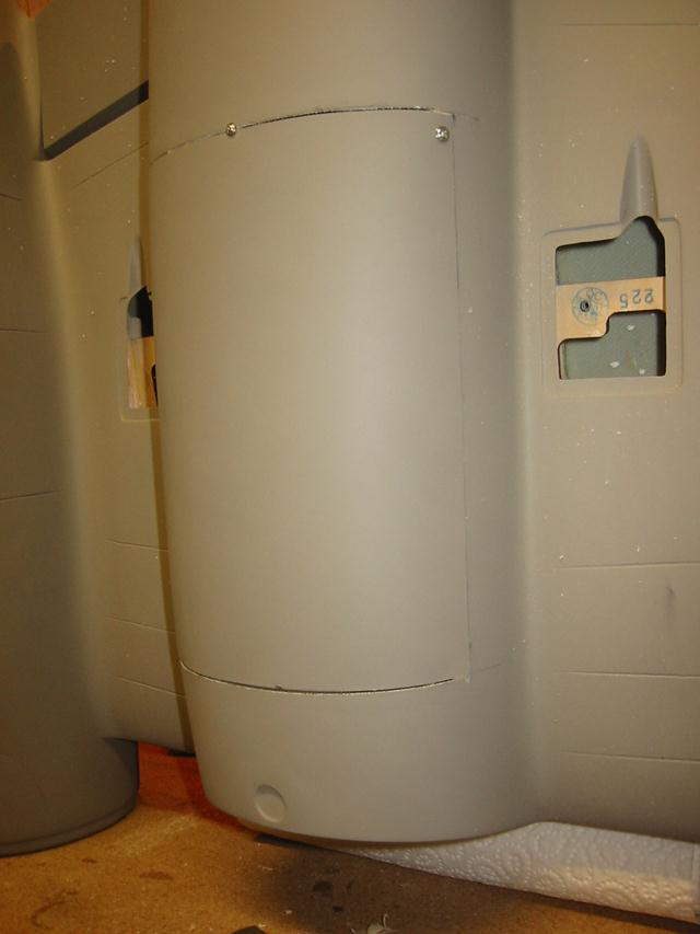
Tank (or bomb...) hatch closed. Just “good enough” fit...
Tail with rudder and elevator
I don’t use any of the supplied hardware in the fuse: I replaced by a pull-pull for the rudder, making the tail wheel a slave to the rudder instead of the opposite, and a Sig graphite rod for the elevator. I also modified the servo mounting in order to get the rods in the centre of the fuse. I lifted the elevator servo to allow the rod pass over the rudder servo.
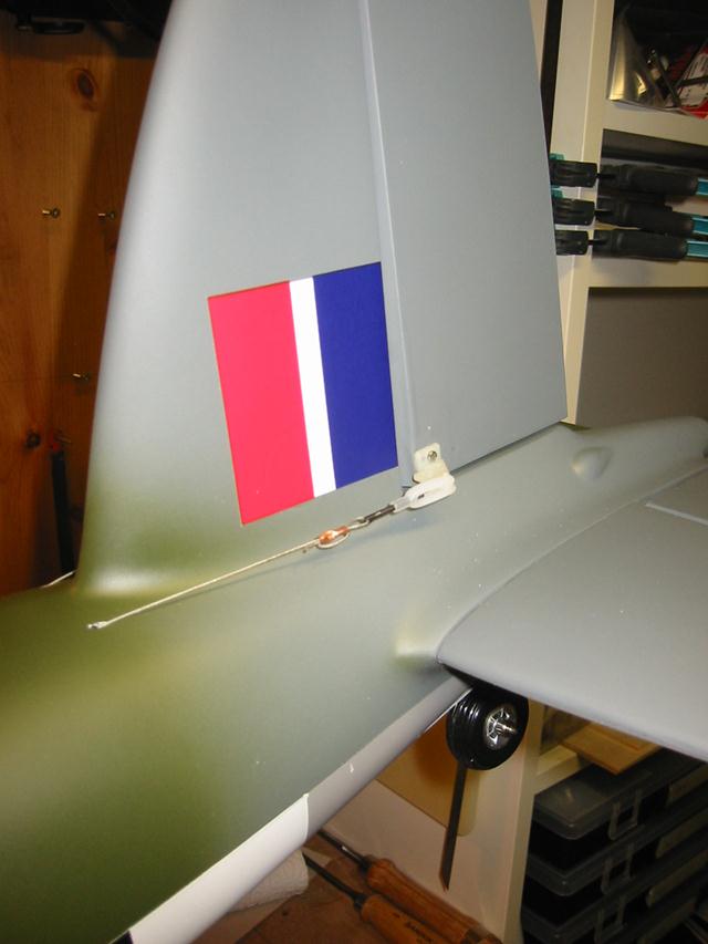
Rudder pull-pull...
... elevator actuators...
... graphite rod end...
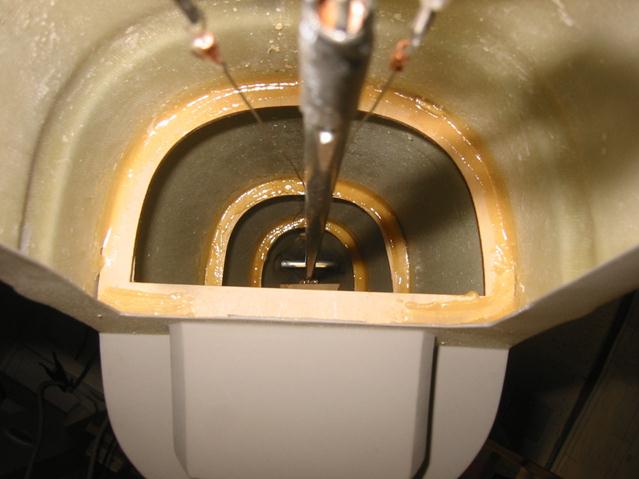
...the rear of the fuse with pull-pull wires and elevator rod...
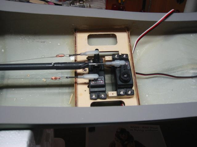
... and the two fuse servos. No, the servo arms don’t touch.
Engine installation
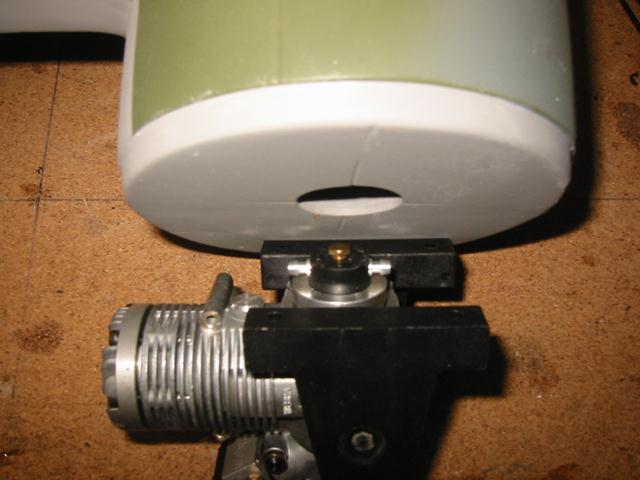
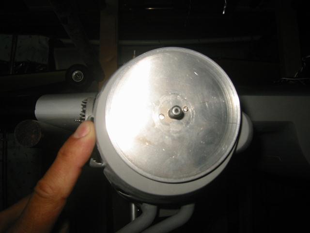
Detail of the rear mounted pump; some mod of the firewall is required.
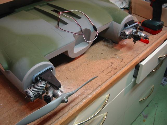
Engines temporarily mounted
Flaps and Wing Panel fixing
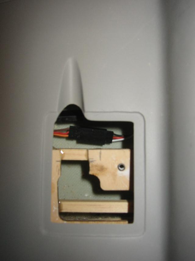
Flap bell crank compartment modified to receive a micro-servo instead of the bell crank
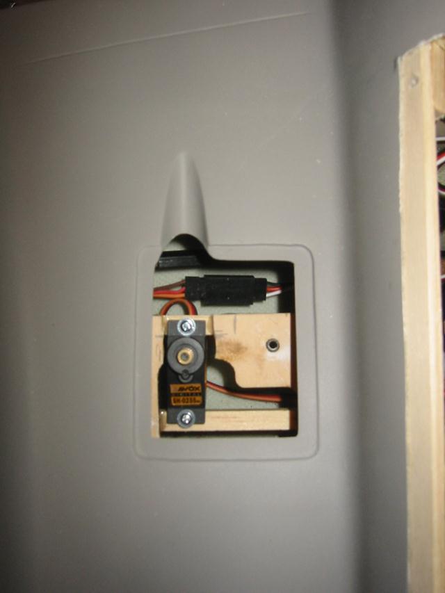
Right flap servo mounted
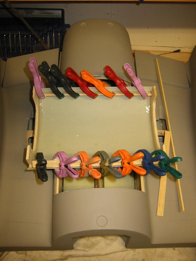
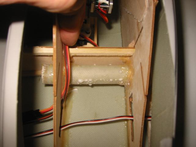
Before mounting the flaps the wing panels need to be glued. I did one panel at the time and I started with the left panel since it had a really tight fit and could not be adjusted at all. Before applying or mixing any glue I built a small jig with balsa blocks, pieces of foam and other small pieces I had lying around.
I applied expanding PU glue to the dowel (just wetting) and the tubes it goes into and then I mixed 30 minute epoxy for the flat surfaces. Unfortunately I was too busy to take pictures during the operation. You can see on the pic below that the amount of PU glue is sufficient to fill the dowel seat; the PU is sweating through the fiberglass tube.
I used the same jig material for the second paned and adjusted everything to be identical to for the first. Please note that when the central wing section in put on the table you need to make sure it’s flat on the table. I needed to put 4mm under the front of the right nacelle.
Now it was time to fix the flaps. The flap joining wire had a lot of play thus I put some glue (epoxy would be fine) in the holes were the wires sit. Note that fixing the two flap surfaces on one side is a single operation; both outer and inner flap surface need to be fixed at the same time.
Having fixed the flaps I painted the invasion stripes. I regret I didn’t paint them on the loose wing panels. It would have been much easier even though in this case the outer flap in not fixed yet... After the stripes I put a matte clear coat on the whole airframe since I felt the paint was really abrasive and fragile.
The result is here:
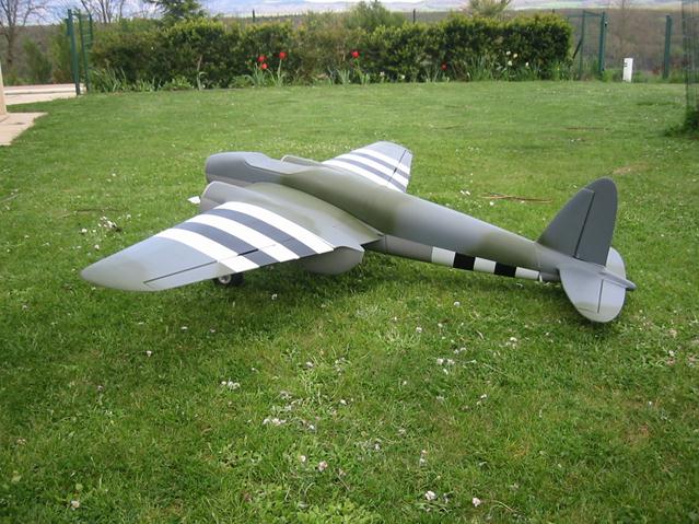
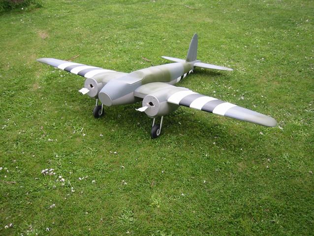
I’m quite happy with the result but don’t look too close, please....
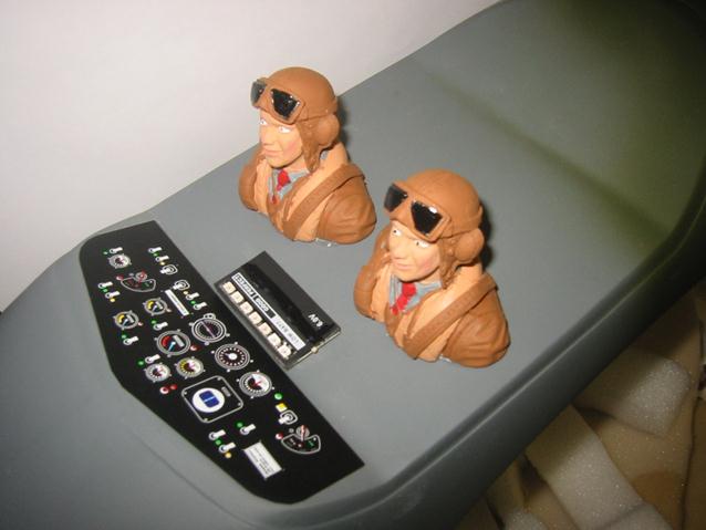
I finally got around to painting the twin pilots. I ran them through the dishwasher first in order to get the silicon layer off them and used Humbrol acrylics. Note the strange look in the twin’s eyes; without any doubt due to tension in view of the maiden flight. Also the non-regular red ties to celebrate the maiden flight…
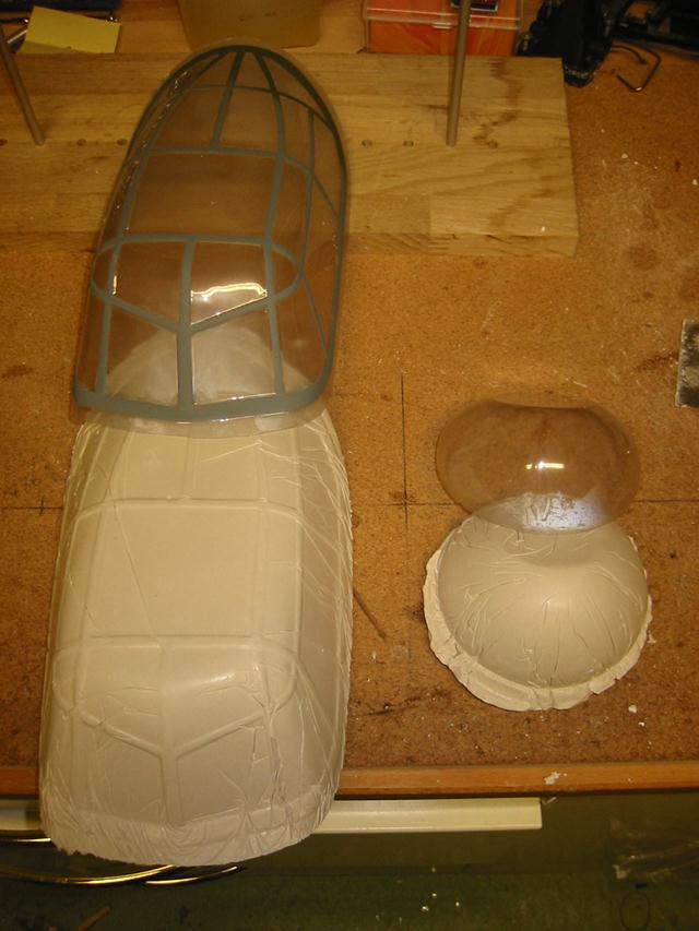
As usual I made moulds for the canopies, just as insurance against mishaps… J
Cowls
Aaarrrgggghhhhh!!! The spinner does not lien up to the cowl! In the end, 3mm left, 6mm down made the trick. Please see lessons learnt below.
Engine testing
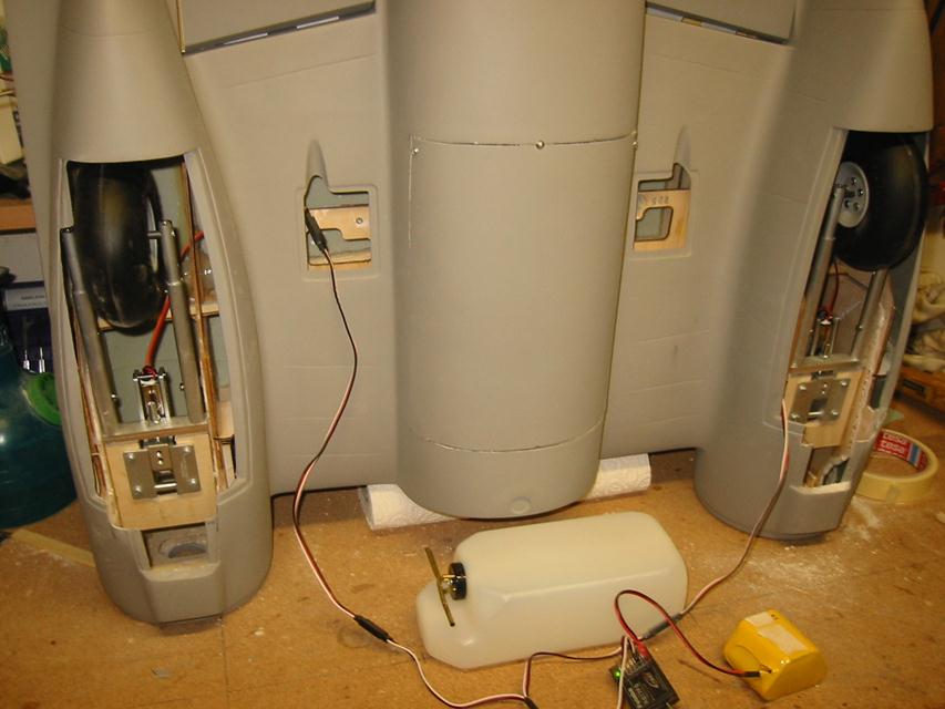
Having a particular tank arrangement I decided to pre-adjust the engines (pumps, carbs, long fuel lines, etc.) and I built a hammerhead engine test stand:
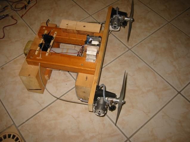
I’ll run a few litres through to verify the good functioning of the concept.
By the way, the test stand uses “Futaba S3003” servos bought cheaply on ebay. I planned to use them for a cheap plane. These servos are obviously not Futaba servos and they are so bad that I would not put them in anything I spent more than 20 $/Euro and 30 minutes on and that’s pretty much – nothing... I use them here since I don’t want to just throw them away. Perhaps I can take out the preamps and use them for lighting or something.
A test run of the hammerhead with straight FAI fuel confirmed many things:
1) A pumped
engine with dynamix carb can be a bitch to adjust
1b) two engines running at the same time does not make it easier at all
2) Two two-cycle engines at full pitch with bisson pitts mufflers is LOUD.
But also:
3) two engines on one tank far away appear very
feasible
4) when running dry they quit within 5 seconds
from eachother
5) 20oz is plenty for two .40 size engines
6) the two engines will
certainly fly the plane; I get 12500 rpm +/- 50 at full blast with APC 11x5
props. The hammerhead almost took off.
7) the two engines are
very similar; with equal carb opening they deliver very close RPM.
8) The pump
arrangement seems to enhance reliability: if the engine hesitates due to for
example lean idle the pump will push fuel into the carburettor making it very
rich; 99% chance for the engine to come back alive. Again, the price to pay is
reliability but of a different kind: after a long time on the shelf the pump
may not function properly and need service; this, however, is easy to detect on
the ground and then – don’t fly...
Lessons Learnt, or What I would do differently
1. The cowls and the engines (spinners…) do not automatically line up and the marks on the nacelles were simply wrong on my kit. I recommend fixing the cowls first, and then centre the engines to the cowls. Mine where 3mm off horizontal and 6mm off vertical. Please do ALL this before fixing the wing panels. I did not L.
2. I would consider painting the invasion stripes before fixing the wing panels on the centre piece.
3. I would consider throwing out the aluminium dowels and get longer ones; I would drill out the bottom of the dowel seat in the wing centre etc and make the longer dowels meet in the centre of the wing and thus gain significantly in strength.
Rcuniverse posts under name fast_mag:
http://www.rcuniverse.com/forum/m_2007938/mpage_54/key_/tm.htm#
http://www.rcuniverse.com/forum/m_2007938/mpage_55/key_/tm.htm#
http://www.rcuniverse.com/forum/m_2007938/mpage_56/key_/tm.htm#